Lou's Pseudo 3D Page
 |
Pseudo 3d en español aqui! Gracias a Luis Peña!
(C) 2013 Louis Gorenfeld, updated May 3, 2013
NEW: Important details on the segmented road system and some additional links
NEW: An (optional) explanation of finding field-of-view for the 3d projection formula
NEW: An analysis of S.T.U.N. Runner
NEW: General writing improvements
Previous update:
An explanation of 3d projection mathematics (under Road Basics) and analysis of Activision's Enduro (under Case Studies)!
Thanks to everyone for all the e-mail! Keep it coming :)
Sorry, I can't answer questions about when I'll post source code, but I'm
always happy to answer anything else about these engines!
Official material on the Road Rash graphics engine and more detailed explanation of curves and a generalized curve equation
Is this information inaccurate? Am I way off? Don't hesitate to write me at louis.gorenfeld at gmail dot com!
Table of Contents
IntroductionRoad Basics
Curves and Steering
Sprites and Data
Hills
Taking Raster Roads Farther
True 3d-Projected Segments
Enhancements
Related Effects
Case Studies
Code Stuff
Glossary
The Gallery
Introduction
Why Pseudo 3d?
Now that every system can produce graphics consisting of a zillion polygons on the fly, why would you want to do a road the old way? Aren't polygons the exact same thing, only better? Well, no. It's true that polygons lead to less distortion, but it is the warping in these old engines that give the surreal, exhillerating sense of speed found in many pre-polygon games. Think of the view as being controlled by a camera. As you take a curve in a game which uses one of these engines, it seems to look around the curve. Then, as the road straightens, the view straightens. As you go over a blind curve, the camera would seem to peer down over the ridge. And, since these games do not use a traditional track format with perfect spatial relationships, it is possible to effortlessly create tracks large enough that the player can go at ridiculous speeds-- without worrying about an object appearing on the track faster than the player can possibly react since the physical reality of the game can easily be tailored to the gameplay style.
But they have plenty of drawbacks as well. The depth of physics found in more simulation-like games tends to be lost, and so these engines aren't suited to every purpose. They are, however, easy to implement, run quickly, and are generally a lot of fun to play with!
It is worth noting that not every older racing game used these techniques. In fact, the method outlined here is only one possible way to do a pseudo 3d road. Some used projected and scaled sprites, others seem to involve varying degrees of real projection for the road. How you blend real mathematics with trickery is up to you. I hope you have as much fun exploring this special effect as I did.
How Much Math Do I Need?
If you...
...have Trigonometry knowledge, that's the most math you'll need for the entire tutorial
...have just Algebra and Geometry, skip the field-of-view explanation
...want to avoid as much math as possible, read: The Simplest Road, Curves and Steering, Sprites and Data, and Hills
This is a very flexible technique, and you can actually get by with just addition! With more advanced math, it can look better, but with just arithmetic, you can get up to the level of detail seen in games like Pole Position or the first OutRun.
How Much Programming Knowledge Do I Need?
It helps a lot to understand raster graphics: Know what a scanline is, and that each line is made of a row of pixels.
The programming examples are written in pseudocode, so you don't need experience in any specific language to understand them.
Ready? Let's begin!
Raster Effects - Some Background
A pseudo 3d road is just a variation of a more general class of effects called raster effects.
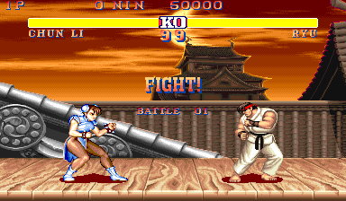
One of the best-known examples of a raster effect is in Street Fighter II:
As the fighters move left and right, the ground scrolls in perspective. This actually isn't 3d. Instead, the ground
graphic is stored as an extremely wide-angle perspective shot. When the view scrolls, the lines of the screen which are supposed to be farther away scroll more slowly than the lines which
are closer. That is, each line of the screen scrolls independently of each other.
Shown below is both the end result and the ground graphic as it is stored in memory.

Road Basics
Introduction to Raster Roads
We are used to thinking of 3d effects in terms of polygons whose vertices are
suspended in 3d space. Older systems, however, were not powerful enough to
make a large number of 3d calculations. Many older effects, in general,
fall into the category of raster effects. These are special effects which
are done by changing some variable per line. Most commonly, this means changing
the color or palette per line, or scrolling per line. This is well-suited to
old graphics hardware which had acceleration for scrolling and used an indexed
color mode.
The pseudo raster road effect actually works similarly to the Street Fighter II perspective effect in that it warps a static image to create the illusion of 3d. Here's how they do it:
Most raster roads start off with an image of a flat road. This is essentially a graphic of two parallel lines on the ground retreating into the distance. As they get farther into the distance, the lines appear to the viewer to be closer together. This is a basic rule of perspective. Now, in order to give the illusion of motion, most arcade racing games have stripes on the road. Moving these stripes on the road forwards is generally either achieved by color cycling or by changing the palette every line. Curves and steering are done by scrolling each line independently of one another, just like in Street Fighter II.
We will get into curves and steering in the next chapter. For now, let's put that aside and concentrate on making the road appear to scroll forwards.
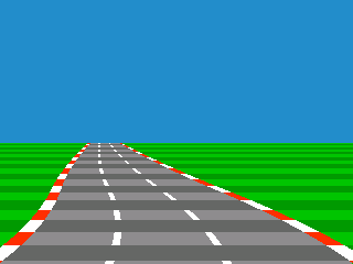
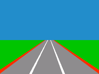
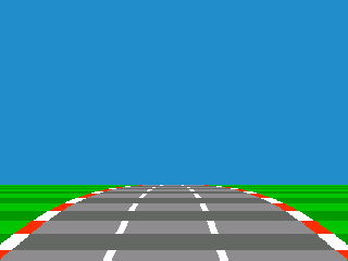
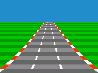
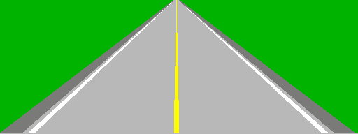
The Simplest Road
Take the image of a road described above: Two parallel lines demarcating the left and right edges of the road
retreat into the distance. As they move into the distance, they appear to the viewer to be closer together.
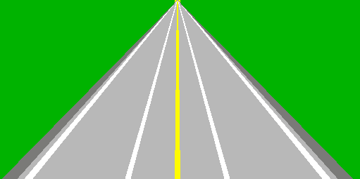
Below is what this might look like:
What is missing from this picture are road markings to give a good impression of distance. Games use alternating light and dark strips, among other road markings, for this effect. To help accomplish this, let's define a "texture position" variable. This variable starts at zero at the bottom of the screen and increases each line going up the screen. When this is below a certain amount, the road is drawn in one shade. When it is above that amount, it is drawn in the other shade. The position variable then wraps back to zero when it exceeds the maximum amount, causing a repeating pattern.
It is not enough to change this by a set amount each line though, because then you'll just see several strips of different colors which are not getting smaller as the road goes into the distance. That means you need another variable which will change by a set amount, add it to another variable each line, and then add the last one to the texture position change.
Here's an example which shows, from the bottom of the screen, what the Z value will be for each line as it recedes into the distance. After the variables, I print what is added to get the values for the next line. I've named the values DDZ (delta delta Z), DZ (delta Z), and Z. DDZ remains constant, DZ changes in a linear fashion, and Z's value curves. You can think of Z as representing the Z position, DZ as holding the velocity of the position, and DDZ as being the acceleration of the position (the change in acceleration). Note that the value I chose, four, is arbitrary and was just convinient for this example.
DDZ = 4   DZ = 0   Z = 0  : dz += 4, z += 4

DDZ = 4   DZ = 4   Z = 4  : dz += 4, z += 8

DDZ = 4   DZ = 8   Z = 12 : dz += 4, z += 12

DDZ = 4   DZ = 12  Z = 24 : dz += 4, z += 16

DDZ = 4   DZ = 16  Z = 40 : etc...
Noice that DZ is modified first, and then that is used to modify Z. To sum it up, say you are moving through the texture at speed 4. That means that after line one, you are reading the texture at position 4. The next line will be 12. After that, 24. So, this way it reads through the texture faster and faster. This is why I like to refer to these variables as the texture position (where in the texture we are reading), the texture speed (how quickly we read through the texture), and the texture acceleration (how quickly the texture speed increases).
A similar method will also be used to draw curves and hills without too much number crunching. Now, to make the road appear to move, just change where the texture position starts at the bottom of the screen for each frame.
Now, you may notice a shortcoming with this trick: the zooming rate is inaccurate. This causes a distortion that I will refer to as the "oatmeal effect". It is a warping effect present in early pseudo games such as OutRun in which objects, including the stripes on the road, appear to slow down as they move outwards from the center of the screen.
This method for finding the Z value has another disadvantage: It's not easily predictable what the value is in the very distance, especially when hills are involved. We will learn a more advanced method which I will call the Z-map. This is a table that calculates what the Z distance is for every scanline of the screen. But first, we need a little more math...
A Mathematical Detour: 3d Perspective Projection
There are ways to get rid of the oatmeal effect. However, some traditional 3d mathematics are needed to make them possible. What we need is a way of translating
3d coordinates so that they fit onto a 2d surface.
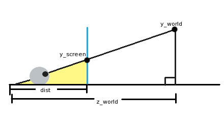
In the picture above, an eyeball (lower left) is looking through the screen (the blue vertical line) at an object in our 3d world ("y_world"). The eyeball is a distance "dist" from the screen, and a distance "z_world" from the object. Now, one thing you might have noticed if you've spent some time with geometry or trigonometry is that there are not one but two triangles in the picture. The first triangle is the largest one, from the eyeball over to the ground on the right side and up to the object we're looking at. The second triangle I've colored yellow. This is from the eyeball to where on the screen we'll see our object, down to the ground, and back.
These two triangles' hypoteneuses (the line from the eye to the object) are at the same angle even though one is longer than the other. They are essentially the same triangle, but the smaller one is just scaled down. What this implies is that the ratio of the horizontal and vertical sides must be the same! In math terms:
y_screen/dist = y_world/z_world
What we need to do now is juggle the equation to get y_screen. This gives us:
y_screen = (y_world*dist)/z_world
In summary, to find the y coordinate of an object on the screen, we take the y world coordinate, multiply that by the distance we are to the screen, and then divide it by the distance it is in the world. Of course, if we just do that, the center of our view is going to be the upper-left corner of the screen! Just plug in y_world=0 to see this. What we can do to center it is add half of our screen resolution to the result to put it right in the middle. The equation can also be simplified a little bit by pretending that our noses are right up to the screen. In this case, dist=1. The final equation then is:
y_screen = (y_world/z_world) + (y_resolution/2)
There is a relationship between the ratios and the viewing angle, as well as scaling the image so that it is resolution-neutral, but we won't really need any of that to fix our road problem. If you are curious, try looking at the diagram from the top view: the angle to the edge of the screen is the field of view and the same relationships hold!
More Math: Adding Field-of-View to 3d Projection
Now, this is largely unnecessary for most road engine cases. But, it's useful for making projection parameters
resolution-independent, or for objects that need to rotate or for integration with true 3d effects.
Let's go back to the original projection formula. The "dist" from the explanation above will now be called "scaling":
y_screen = (y_world*scaling)/z_world + (y_resolution/2)
The idea is that we need to scale all the points on the screen by some value which lets points within a certain field-of-view (FOV) remain visible. You'll need a constant for the x FOV and a constant for the y FOV.
As an example, let's assume we're working in 640x480 resolution and we want a FOV of 60 degrees. We've seen a diagram of
3d projection from the side view. For this, let's look at this
top view of the projection space instead:
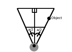
One way to think about the problem is that if an object is at the right edge of our FOV, it needs to appear on the screen
at x=640 (since we're at 640x480). Looking at the chart, our FOV can be split into two right triangles where the angle
of each is fov_angle/2 (a/2). And since our FOV is a cone, an object is on the right edge of its FOV if its x=R*sin(a/2) and
z=R*cos(a/2), where R is any radius value we want. We might as well make R=1. And we need the object to appear at
x_screen=640.
That gives us this (starting from the basic projection formula):
	x_screen=640   fov_angle=60   y_world=sin(60/2)    z_world=(60/2)    x_resolution/2=320    scaling=?


x_screen = (y_world*scaling)/z_world + (x_resolution/2)

640 = (sin(30)*scaling/cos(30)) + 320

320 = tan(30)*scaling

320/tan(30) = scaling


In generic terms: scaling = (x_resolution/2) / tan(fov_angle/2)
We've replaced a/2 by 30 (half of 60 degrees), recognized that sin/cos = tan, and voila! We should be able to test this by placing an object at the right edge of the field-of-view, plugging these values into the original projection equation, and ensuring that the X value winds up as 640. For example, an (x, z) point at (20, 34.64) will wind up at X=640 because 20 is 40*sin(30) and 34.64 is 40*cos(30).
Note that you'll have different FOV values for horizontal (x) and vertical (y) for a standard or widescreen monitor that's in horizontal orientation.
A More Accurate Road - Using a Z Map
What we want to do to fix our perspective problem is to precompute a list of distances for each line of the screen. In short, the problem is how to describe a flat plane in 3d.
To understand how this works, first think of the 2d equivalent: a line! To describe a horizontal line in 2d, you would say that for every (x, y) coordinate the y is the same.
If we extend this into 3d, it becomes a plane: for every x and z distance, the y is the same! When it comes to a flat horizontal surface, it doesn't matter how far from the camera it is, the
y is always the same. Likewise, it doesn't matter how much to the left or right the point is, the y will still be the same.
Back to figuring out the distance of each line of the screen: let's call this a Z Map. Calculating the Z Map is just a matter of rearranging the 3d
projection formula to find a Z value for each screen Y!
First, take the equation from the last section:
Y_screen = (Y_world / Z) + (y_resolution / 2)
Now, since we're given Y_screen (each line), juggle the equation so that we're finding the Z:
Z = Y_world / (Y_screen - (height_screen / 2))
Y_world is basically the difference between the ground and the camera height, which is going to be negative. This is the same for each line because, as described in the introductory paragraph, we're interested in a flat road for the time-being. In addition to looking much more accurate and avoiding the "oatmeal effect", it has the advantage that it is easy to compute what the maximum draw distance is.
The road is mapped onto the screen by reading through this buffer: For each distance, you must figure out what part of the road texture belongs there by noting how many units each stripe or pixel of the texture take up.
Though we now know the distance of each row of the screen, it may also be useful to cache either the width of the road or scale factor for each line. The scaling factor would just be the
inverse of the distance, adjusted so that the value is 1 on the line which the player's car graphic spends the most time. This can then be used to scale sprites which are on a given line, or to
find what the width of the road is.
Curves and Steering
Making it Curve
To curve a road, you just need to change the position of the center-line in a curve shape. There are a couple ways to do this.
One way is to do it the way the Z positions were done in "The Simplest Road": with three variables. That is, starting at the bottom of the screen, the amount that the center of the road shifts left or right per line steadily increases. Like with the texture reads, we can refer to these variables as the center line (curve) position, the curve velocity, and the curve acceleration.
There are some problems with this method though. One is that S-curves are not very convinient. Another limitation that going into a turn looks the same as coming out of a turn: The road bends, and simply unbends.
To improve the situation, we'll introduce the idea of road segments. A road segment is a partition which is invisible to the player. Think of it as an invisible horizontal divide which sets the curve of the road above that line. At any given time, one of these segment dividers is at the bottom of the screen and another is travelling down at a steady rate towards the bottom of the screen. Let's call the one at the bottom the base segment, because it sets the initial curve of the road. Here's how it works:
When we start drawing the road, the first thing we do is look at the base point and set the parameters for drawing accordingly. As a turn approaches, the segment line for that would start in the distance and come towards the player kind of like any other road object, except it needs to drift down the screen at a steady rate. That is, for a specific speed that the player is traveling, the segment divider travels down the screen at so many lines per frame. Or, if you're using a Z-Map, so many z-map entries per frame. If the segment were to 'accelerate' at the player the way 3d objects on the track do, the road would swing too wildly.
Let's see how this works. Suppose the segment line for a left curve is halfway down the road and the base segment is just a straight road. As the road is drawn, it doesn't even start curving until it hits the "left curve" segment. Then the curve of the road begins to change at the rate specified by that point. As the moving segment hits the bottom of the screen, it becomes the new base segment and what was previously the base segment goes to the top of the road.
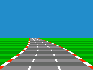
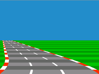
Shown below are two roads: One is a straightaway followed by a left turn, and one is a left turn followed by a straightaway. In both these cases, the segment position is halfway down the Z Map (or, halfway down the screen). In other words, the road begins to curve or straighten halfway down the road, and the camera is entering the turn in the first picture and leaving the turn in the second.
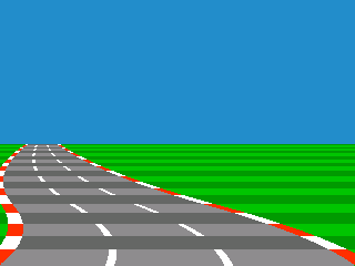
And this is the same technique and same segment position applied to an S-curve:
The best way to keep track of the segment position is in terms of where on the Z Map it is. That is, instead of tying the segment position to a screen y position, tie it to a position in the Z Map. This way, it will still start at the road's horizon, but will more gracefully be able to handle hills. Note that on a flat road that the two methods of tracking the segment position are equivalent.
Let's illustrate this with some code:
current_x = 160  // Half of a 320 width screen

dx = 0 // Curve amount, constant per segment

ddx = 0 // Curve amount, changes per line


for each line of the screen from the bottom to the top:

  if line of screen's Z Map position is below segment.position:

    dx = bottom_segment.dx

  else if line of screen's Z Map position is above segment.position:

    dx = segment.dx

  end if

  ddx += dx

  current_x += ddx

  this_line.x = current_x

end for


// Move segments

segment_y += constant * speed // Constant makes sure the segment doesn't move too fast

if segment.position < 0 // 0 is nearest

  bottom_segment = segment

  segment.position = zmap.length - 1 // Send segment position to farthest distance

  segment.dx = GetNextDxFromTrack() // Fetch next curve amount from track data

end if
One big advantage of doing the curves this way is that if you have a curve followed by a straightaway, you can see the straightaway as you come out of the curve. Likewise, if you have a curve followed by a curve in the opposite direction (or even a steeper curve the same direction), you can see that next piece of track coming around the bend before you hit it.
To complete the illusion, you need to have a horizon graphic. As the curve approaches, the horizon doesn't change (or scrolls only slightly). Then when the curve is completely drawn, it is assumed that the car is going around it, and the horizon scrolls quickly in the opposite direction that the curve is pointing. As the curve straightens out again, the background continues to scroll until the curve is complete. If you are using segments, you can just scroll the horizon according to the settings on the base segment.
General Curve Formula
There is one interesting observation we can make about the curve technique detailed in the section "The Simplest
Road". This observation is more mathematical than the above-material, and can be safely skipped as long as your
graphics engine either does not have to be resolution-independent or is using the "3d projected segments" technique
discussed in the chapter on hills.
Looking at the curve example using "Z" from the section "The Simplest Road", we can see that the z-position (or x-position) at a given line is the sum of an increasing series of numbers (e.g. 1 + 2 + 3 + 4). This is what's called an arithmetic series, or an arithmetic progression. Instead of 1 + 2 + 3 + 4, a sharper curve can be produced by adding 2 + 4 + 6 + 8, or 2*1 + 2*2 + 2*3 + 2*4. The "2" in this case is the variable segment.dx from above. It can also be factored out to get 2(1 + 2 + 3 + 4)! Now all that has to be done is to find a formula to describe 1 + 2 + ... + N, where N is the number of lines making up the curve. It turns out that the sum of an arithmetic series is equal to N(N+1)/2. So, the formula can be written as s = A * [ N(N+1)/2 ] where A is the sharpness of the curve and s is the sum. This can be further modified to add a starting point, for instance, the center of the road at the bottom of the screen. If we call this 'x', we now have s = x + A * [ N(N+1)/2 ].
We now have a formula to describe our curve. The question that we want to ask it is, "given a starting point x and N lines of the curve, what should A be to make the curve reach x-position 's' by the end?" Juggling the equation to solve for A gets us A = 2(s - x)/[n(n+1)]. This means that the sharpness of a given curve may be stored in terms of the endpoint's X position, making the graphics engine resolution-independent.
Perspective-style Steering
It's much less interesting looking to have a game in which when you
steer, it only moves the car sprite. So, instead of moving the player's car sprite, you keep it in the center of the screen and move the road-- more importantly, you move the position of the center-line at the front (bottom) of the screen. Now, you want to assume that the player is going to be looking at the road always, so make the road end at the center of the screen. You'll need an angle-of-road variable for this. So, calculate the difference between the center of the screen and the position of the front of the road, and divide by
the height of the road's graphic. That will give you the amount to
move the center of the road each line.
Sprites and Data
Placing Objects and Scaling
Sprites should be drawn back-to-front. This is sometimes referred to as the Painter's Algorithm. To do this, you'll have to note in advance where on the screen each object should be drawn, and then draw them in a different step.
The way I do this is as follows: As I go through the Z Map while drawing the road, I like to also note at that time which line of the screen each sprite
will be associated with. If you've kept your sprites sorted by Z, this is trivial: Each time a new Z Map value is read,
check to see whether the next sprite's Z position is closer to the camera than the current Z Map value, or whether it's
equal. If so, note that sprite's screen Y position as belonging to the current line. Then check the next sprite the
same way. Keep doing this until you take a sprite off the list which has a farther Z position than the current one.
The X position of the object should be kept track of relative to the center of the road. The easiest way then to position the sprite horizontally is just to multiply it by the scaling factor for the current line (inverse of Z) and add that to the road's center.
Storing Track Data
When I did my first road demo, I stored the level information as a list of events which would happen at specified distances. The distances are, of course, in terms of texture position units. The events would consist of commands to begin and stop curves. Now, as far as I can tell, the speed at which the road starts and stops curving is arbitrary. The only rule seems to be that it must correlate to the speed of the player vehicle.
If, however, you are using a segmented system, you can just use a list of commands. The distance that each command takes is equivalent to how quickly the invisible segment line drifts down the screen. This also frees you up to create a track format which works on a tile map, for representing somewhat realistic track geography. That is, each tile could be one segment. A sharp turn could turn the track 90 degrees, while a more mild turn would come out at 45 degrees.
Texturing the Road
Now, you probably would like a real graphical texture on your road
instead of the alternating lines and such that you have at the moment.
There are a couple ways to do this. A cheap and easy way to do it is this: You have a couple of textures for the road (for the alternating line effect).
When each horizontal line of the road is drawn, you stretch the texture to fit the width of that line. Or, if you can't stretch, pick a line out of one of two complete road
bitmaps (ala Outrunners).
If you want the road to look more accurate, make the Z for each line correspond to a row number on a texture graphic. Voila! One textured road!
However, if you only want strips of alternating color, the answer is even simpler-- especially when using fixed point. For each Z, make one of the bits
represent the shade of the road (dark or light). Then, just draw the appropriate road pattern or colors for that bit.
Hills
Varieties of Hills
It seems there are a near-infinite number of ways to produce hill effects. Hill effects have a wide range of geometric accuracy, with some of the
less accurate techniques being more convincing than others. Here we will examine two possible methods.
Faked Hills
After much experimentation, I've come up with a flexible method for faking hills which uses little in the way of
calculations. Additionally, it accurately tracks objects which are beneath the horizon. It is a scaling
and warping effect which vertically stretches and compresses the road. It uses the same addition trick
used to draw the curves to generate the curvature of the hill.
Here's how it's done: First of all, the drawing loop would start at the beginning of the Z Map (nearest) and stop when it gets to the end (farthest). If we are to decrement the drawing position each line by 1, the road will be drawn flat. However, if we decrement the drawing position each line by 2, doubling lines as we go, the road will be drawn twice as high. Finally, by varying the amount we decrement the drawing position each line, we can draw a hill which starts flat and curves upwards. If the next drawing position is more than one line from the current drawing position, the current Z Map line is repeated until we get there, producing a scaling effect.
Downhills are similar: If the drawing position is incremented instead of decremented, it will move beneath the last line drawn. Of course, lines which are below the horizon will not be visible on-screen-- only lines which are 1 or more pixels above the last line should be drawn. However, we'll still want to keep track of objects which are beneath the horizon. To do this, note the screen Y position of each sprite as the Z Map is traversed. It may help to make the Z Map larger than needed for a flat road. This way, as the buffer stretches, it won't become too pixellated.
Now, we have to move the horizon to convince the player. I like to use a Lotus-style background in which the horizon doesn't just consist of just a skyline, but also a distant ground graphic. When the hill curves upwards (elongating the view), the horizon should move downwards slightly relative to the top of the road. When the hill curves downwards as the camera crests the hill (shortening the view), the horizon should move upwards.
This is what the effect looks like for a downhill and an uphill-- minus the horizon graphic of course:
Pros
- Inexpensive in terms of calculations: No multiplies or divides necessary
- Objects on the back side of the hill are tracked
- The view's angle appears to follow the player over hills
- Accurate 3d geometry is impossible
- Tweaking is required to create a convincing effect
Wrap-up: Taking Raster Roads Farther
These accumulation-style curve formulas can be used verbatim if you don't need crazy curves or huge, rolling hills. Many games which use these kinds of tricks scroll the road so fast that even a slight curve can be convincing.However, you may want to exaggerate the effect in order to get a more dramatic road. One thing that can be done with any of these curve formulas is to use high ddx or ddy values, but not allow dx or dy to exceed a sane value. And a user on YouTube, Foppygames, has discovered another trick for getting more severe curves out of these accumulation formulas: multiply the dx or dy value by the z value for each line! This makes the curve more severe in the distance than it is in the foreground, and it creates a pretty convincing effect.
And, the experimentation doesn't stop there. In fact, the best thing about these engines is that there's no "right" way of doing it. Anything that creates curves and warpage which is pleasing to the eye is allowed! In my earliest road engines, I used a sinewave lookup table to bend the road.
You can also use multiplication: To shift the road right, you might multiply the x position by, for example, 1.01 each line. To move it left the same amount, you'd multiply it by 0.99, or 1/1.01 (reciprocal of 1.01). However, armed with the knowledge that many old processors did not have multiplication or were slow at it, I settled upon using the accumulation technique because it only uses addition. It seemed the most likley "authentic" way of curving the road.
Some games, like OutRun, even use a simple spline system-- at least judging by the great reverse-engineered open-source C++ port, Cannonball.
So, play around and experiment, and see what technique you like best!
...or, read on for a description of a clever trick that mixes 3d polygons, is nearly as fast, is even more convincing,
and can be displayed with the same oldschool raster hardware. Intrigued?
True 3d-Projected Segments
3d-Projected Segments vs. Raster Roads
As nice as raster roads are, they can be made even more impressive by involving a simple form of polygon rendering. This form of rendering
can actually be pulled off using the same limited raster hardware. However, it involves more calculations.
This trick is known to have been used in games such as Road Rash and Test Drive II: The Duel. Here's what it is: The track is made of polygonal segments. However, rather than moving in full 3d space, it still only moves towards the camera. For curves, the road still just skews left and right in almost an identical way to the raster road: There is no actual rotation when going around curves as there would be in a full polygonal engine.
Here's a rundown:
- Since we are still faking curves and road angles, that means expensive rotation calculations still won't be needed
- The road is essentially a strip of quads: each section of the road is attached to the next section. This means we can calculate whether part of the road is visible or not based solely on its screen Y position relative to its previous neighbor.
- The relationship of these quads to one another will never change. That is, the angle never actually changes, so the quads are always and automatically sorted by Z.
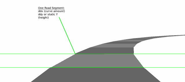
The Basic 3d Road
First, break the road into polygonal quads. Each of these will be called a segment. Just like a segment in a purely raster
road, each segment here still has a curve amount (ddx), and either a hill amount (ddy) or a y-position that determines how high
up it is. Of course, these can also have other attributes as well such as terrain changes.
Pictured below is a segmented road made of very few polygons so we can easily see the boundaries between the segments and how
it affects the curvature of the road:
When rendering, first find the screen y location of each 3d segment by using the screen_y = world_y/z formula. Or, if division is too slow, you could find the height off the ground of a given segment by multiplying the segment's height by the scaling factor for that line. That could then be subtracted that from a reverse z-map (this map would be: for every z position of a flat road, what is the y?) to find the final position on screen.
Then, you would linearly interpolate the road widths and texture (if desired) between these heights. Deciding which 3d segments to draw and which not to can be determined easily: From the front of the screen back, a 3d segment whose screen_y is projected as lower than the last-drawn 3d segment would not be shown (however, its sprites may still be visible because they stick up-- keep that in mind).
Scrolling the Road
Now, we also need to learn how to scroll these segments. Move the entire mess of polygons which make up the road towards the camera. As the frontmost segment's polygon passes through the camera, move the entire road back to its starting point so that it loops.
This is akin to how a scolling 2d tilefield can be made by scrolling up to one tile-worth, and when that is hit all the tiles are
shifted over and new tilemap data is pulled in. In this, we scroll up to one segment-worth, and when that is hit, we move the road
back and pull in new road data.
But there is one last very important detail: Let's say the road is a sharp curve. You might have noticed that as you go around this polygonal curve that it jitters as you cross the segment boundary and the road is subsequently reset. One obvious thing that is happening to cause this is that as you traverse a skewed segment, the camera's center relative to the road changes. That is, by the time you get to the end of that segment, the road is no longer centered. It's as if you're driving on the road at an angle. You might be tempted to fix it by moving the road to center it just as objects' x-positions are linearly interpolated.
However, this is wrong and does not completely solve our problem: If the road were skewed in a straight line, this would be fine. The problem is that our road curves, so the polygons in the distance still are not lined up! Another way to think about it is this: We are approximating a curve using polygonal segments. We want the shape of the curve to be more or less constant even as it scrolls.
Jake over at codeincomplete.com has a great solution for this. Instead of changing the x position as the road as you move across the segment, what about changing the initial dx value from 0 to something that keeps the road in line as you move through the segment? The formula used is this:
dx = -percentage_of_segment_traversed * ddx
The percentage of the segment has to go from 0 to 1.0 and back as the camera crosses the segments.
In mathematical terms, doing this makes the X of the road a function of its Z. In other terms, we're keeping the curve the same shape regardless of how the points which approximate it scroll. The frontmost segment is "pulled into position" with the rest of the road, which then means that the subsequent segments' X position are placed correctly. You can see this clearly if you test it with a road made of few polygons. It solves the following problems as the segment is traversed (assuming the curve's shape does not change):
- It keeps the center of the road (x position) constant
- It adjusts dx so that the next segment starts at an appropriate x-location regardless of the scroll position of the road
This video demonstrates the technique. I've used very few segments and a very sharp curve to demonstrate how this looks. Notice that as the polygons move towards the player that they carve out a perfect curve shape. This is most apparent if you watch the right side of the road.
Placing Sprites
The sprites on that 3d segment would still need to be shown and properly cropped, however-- assuming you're making a custom
renderer and not using a Z-buffer. We can actually draw the sprites as the last step: If a sprite is on a segment which is completely visible,
it does not need to be cropped since it sticks straight up from the ground, which is our only polygon.
But if a sprite is on a segment which is either not visible or partially visible, we can easily crop it. First, find the top of the sprite. Then, every line of the sprite will be drawn until it hits the last visible segment's screen Y position. That is, if there is a segment behind the sprite which is supposed to cover part of it, you stop drawing the sprite when you hit that line. And if the top of the sprite is below the last segment's Y position, the sprite won't be visible at all and will be skipped.
Variations and Rendering Technologies
Now, since we're throwing around the term polygon, you may be tempted to think that you need polygonal rendering routines
to pull this off. Using technologies like OpenGL or a simple trapezoidal drawing routine definitely do work. But even tile and
sprite-based 2d hardware are perfectly capable of pulling this off.
Observe that each road segment's beginning and end are perfectly horizontal. This means that they always start and end on a specific scanline. Much the way the purely pseudo-3d road is rendered on tile hardware by scrolling the flat road graphic as it's being drawn, we can do exactly the same with these 3d segments. For further reading, check out the section called Dedicated Road Hardware. Though it discusses arcade hardware designed from scratch to draw road effects, the same technique can be achieved with basic 2d sprite-tile systems through scrolling the road graphic vertically as well as horizontally.
Further Reading on 3d-Projected Segments
Since my mock-up of this specific variation is underdeveloped, I will point you to Code inComplete's amazing tutorial if you're interested in further details on this technique.
Pros
- Real 3d geometry can be used for the hills, adding greatly to the amount of detail possible
- The system is more consistent: Terrain and road width changes don't need to be done using a separate technique
- There are more calculations involved
- A decent number of segments must be used or the road will look jagged and polygonal
Enhancements
Multiple Roads
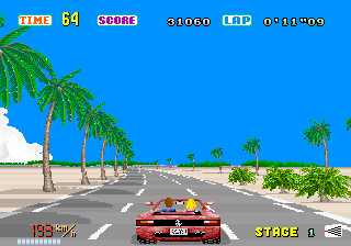
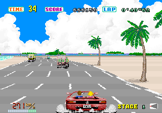
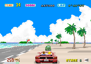
Most arcade racing games handle multiple roads at a time. Though the most obvious reason to do this is to have more than one road on the screen at a time,
other effects can be achieved as well. For example, OutRun uses more than one road to form its six lane freeway. This lets the game widen and narrow
the road easily, as well as convincingly fork. They do this by overlapping the two roads and giving one drawing priority over the other. Here is the
familiar beginning of OutRun both with and without two roads (look to the right of the bushes):
And, even more dramatic, below is the freeway after the two roads are overlapped to form six lanes, both with and without the second road:
Related Effects
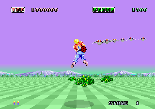
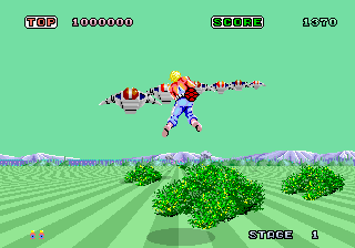
Endless Checkerboard
The endless checkerboard in the arcade game Space Harrier is just a variation on the road technique. Like
a road, the game contains graphics of lines coming at the player in perspective. In fact, Space Harrier
uses the same hardware as Hang-On.
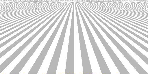
Pictured below is the Space Harrier checkerboard effect with and without the palette changes. To turn this into a checkerboard, all that has to be done is to flip the color palette every few lines. Think of it as analogous to the light and dark strips on a road.
So, how then does it scroll left and right? This is just a variation on perspective-style steering: As the
player moves to the left or right, the ground graphic is skewed. After a few pixels have scrolled past, the ground
"resets" or "wraps" its position. This is how it appears to scroll endlessly to the left and right.
Case Studies
Dedicated Road Hardware
Although there are many ways to render roads, it is interesting to note that many arcade games used hardware designed for this specific purpose.
These chips automate the basics of road drawing, but not the road calculations themselves. As a typical example, I will take Sega's OutRun road
chip, used in games such as Super Hang-on, Outrun and Space Harrier.
First off, the chip has its own graphics memory. What is stored in this road ROM is nearly a perspective view of the road, given that it is flat, centered, and not curving. Then, for each line of the screen, the programmer specifies roughly which line of the perspective graphic to draw there. Each line also has an X offset (for curving the road) and each line can also have a different color palette (to draw road markings and simulate movement). To show an example, here are some images taken from Sega racing game road graphics side-by-side with the road as seen in-game (special thanks to Charles MacDonald for his road viewing application):
 | 
|
 |
|
 |
|
The first thing you might notice is that the road graphics are much higher resolution than the in-game graphics. In these particular games, the road is up to 512x256 resolution while the game's display resolution is only 320x224. This gives the graphics engine plenty of graphic to play with, which cuts down on the amount of jaggies. Another thing which might pop out at you is that the perspective of the road stored in the ROM is completely different from the perspective shown in-game. This is because the graphic in the ROM merely stores what the road might look like for various road widths. It is the job of the program to select the correct lines out of this large graphic for each line of the screen.
The hardware supports two roads at a time, and so you can assign priority to the left or right road. This is for the parts of the game in which the road branches, or when there is a center divider between lanes of traffic.
For you ROM hackers out there, check out MAME's src/mame/video/segaic16.c and src/mame/video/taitoic.c files for examples of road chips. Note that the Sega road graphics are stored in a 2-bit planar format, with the center of the graphic able to sport a fourth color (this is the yellow line shown in the graphics above).
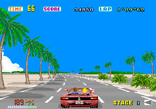
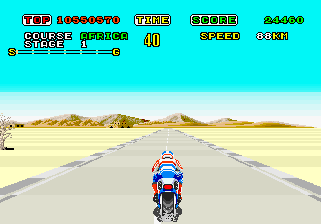
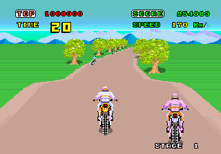
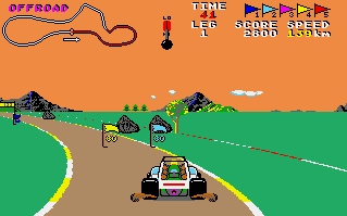
Enduro
Enduro is a remarkable game. Released in 1983 for an incredibly
underpowered 70's gaming console, Enduro still manages to produce a
convincing road effect complete with changing weather and day-night
cycles. On top of that, it manages to be an exciting game even
25 years after its release!
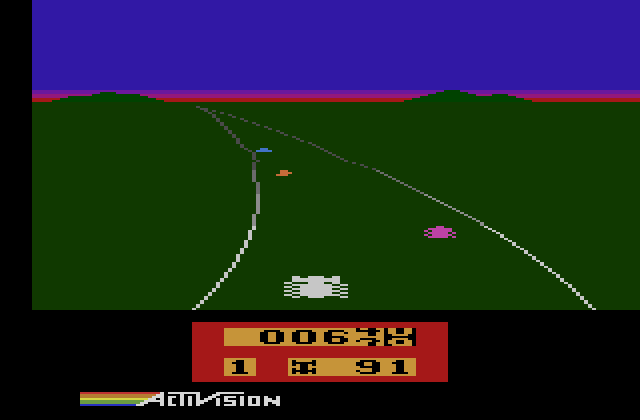
Screenshot of Enduro
As you can see here, Enduro looks a little different from other road engines we've seen so far. Immediately apparant is that the road is only drawn in outline: The terrain to the sides of the road are not drawn in a different color from the pavement. There are also no roadside obstacles. Once you start to play Enduro, you might also notice that the road doesn't move in perspective. Instead, the player car sprite and road both shift left and right to give the illusion of steering.
In order to better understand why Enduro looks the way it does, let's take a peek at the Atari 2600's limitations. The Atari 2600 was designed primarily to play Combat-like games (tank games) and Pong-like games. So, it was capable of displaying: two sprites, two squares representing missiles for each player, a square representing a ball, and a very blocky background. And that's it.
But what's notable about the Atari's video hardware is that it's essentially one-dimensional: the software must update the graphics for each scanline itself. For example, to show a sprite, the programmer has to upload a new line of graphics to display at the beginning of each scanline. To draw the ball object, the programmer would turn on the ball when the TV's beam got to the right line, and turn off the ball when the beam got to a line where the ball should no longer be visible.
This leaves an important side-effect: a solid vertical line can be drawn down the screen by turning on the ball or missiles and then never turning them off! If the programmer moves these objects each line, diagonal lines may be drawn.
Now, back to the task at hand. We could draw the road using the background blocks, but the resolution is much too low to be effective. What Atari driving games did instead was use the two missile or ball graphic objects to draw the left and right sides of the road, much in the same way they can be used to draw lines. Enduro in particular uses the first player's missile sprite and the ball sprite in order to draw the left and right sides. Pole Position, on the other hand, uses both missile sprites for the sides of the road and then uses the ball sprite to draw a dotted line down the center.
Screenshot of Pole Position on 2600 for comparison
One thing I haven't discussed is how you move objects per-line on an Atari 2600. The Atari's graphic chip has a facility called HMOVE (horizontal move). This allows the programmer to set up moves each line for all the different objects very easily. All the programmer has to do is set how many pixels to move for the various objects, and then call HMOVE and voila-- they all move according to what was set!
Enduro exploits this in order to draw curves. In short, what Enduro does create a table in memory of how the HMOVE values of the left and right sides vary as the screen is drawn. This uses almost half of the Atari 2600's available memory. Since the Atari's memory is so tiny, this value is only read every 4 lines. There is a different table for the left and the right sides of the road.
When the road is straight, the array for the right side of the road is all 8's. The HMOVE only uses the upper 4 bits, so 8 loaded into HMOVE wouldn't move the sides of the road at all. The lower 4 bits are used for a crude form of fixed point.
As an example, here's what a curve looks like in memory as it approaches (the
horizon is the end of the array):
08,08,08,08,08,08,0a,0a,0b,0c,0e,0d,0e,0e,0f,10,13,11,12,13,14,17,16,17
And the next frame:
08,08,09,09,0a,0a,0b,0b,0c,0d,0d,0e,0f,0f,10,11,12,12,13,14,15,16,17,18
Note that the higher curve values progressively write over the lower values, shifting down towards the front of the screen to provide the illusion that the curve is coming towards the player. And what does Enduro do with this data? Here's some of the code used to write out the curve for the right side of the road
For each scanline of the road:
LDA $be      ; Load what's in address $be

AND #$0f     ; Blow away the upper 4 bits (the bits HMOVE uses)

ADC $e4,x    ; Add the value from the curve table (X is how far towards the front of the screen we are)

STA $be      ; Save the value again (so we can load it again next scanline like we did above)

STA HMBL     ; Also shove it into the Horizontal Motion - Ball register
So what's this doing? Well, $be is a counter for the curve amount which increments. When it's loaded, the upper 4 bits are tossed overboard, leaving a range of 0 to 16 ($0-F). Then, the curve table entry for that particular scanline is loaded and added in. Finally, it's stored back to the counter and also loaded into the horizontal move register for the ball object (the right side of the road).
This does a few things. First, it only results in the sides of the road moving every two lines when the road is straight: If the array is all 8s and $be contains 0 on the first line, the next line will contain 8 (the upper nybble is still 0). The next line after that will contain $10. But when $10 is loaded back into the register A on the next scanline, the upper nybble is discarded leaving 0 again! This causes the counter to flip between $10 and 8. Since the HMOVE values only use the upper 4 bytes, the line moves 0 positions or 1 positions alternating.
OK, but what if the array is all 9s instead of 8s? Here's what happens: On the first scanline, 9 is stored into the ball HMOVE register and written back to the counter. The next line, 9 is again added to the value from the table making $12 (18 decimal). This will move the ball by 1 (upper 4 bits is 1). On the line after that, the upper nybble is discarded leaving 2. Adding 9 from the table makes $B. Let's look at one more scanline. B is loaded. There is no upper nybble. Adding 9 makes $14 (20).
The sequence described above is 09,12,0b,14. This is still only going to cause the ball to move every other line for these 4 lines. But, eventually the lower nybble is going to become high enough that it will cause the routine to move the ball sprite left two lines in a row. The pattern will then wrap, but after a few more lines, the side of the road will move two lines in a row again. In essence, this is a simple and blazing fast form of fixed point math.
There is another hurdle in implementing a road system on such limited hardware: positioning sprites. On more sophisticated systems, sprites can be positioned horizontally on the road as a percentage of the road width. But this requires either fixed point or floating point multiplication, both of which are extremely slow on a 6502. In contrast, Enduro only has three possible positions for the cars, which saves some calculation.
Road Rash
Road Rash and 3do Road Rash both have amazing graphics engines. The original Genesis version of the game pulled off
a relatively accurate 3d sensation on the Genesis' 7.25mhz 68000 processor, complete with realtime scaling of the
roadside objects. The 3do follow-up is no less fascinating, as it turns out to be a mixture of 3d and pseudo
technique artistically combined to give the player an amazing sensation of speed.
As I mentioned above, both the Road Rash and 3do Road Rash engines are a mixture of 3d and pseudo 3d trickery. They use a technique similar to the one described in the "Realistic Hills Using 3d-Projected Segments" chapter in which the hills are in 3d space, but the road's curves are not. Road Rash's curves use the same method described in this article, and each road segment has its own DDX or "x acceleration" value. Each segment also has a height which is relative to the last segment's height. There are roughly 50 segments on-screen at once.
But where the 3do Road Rash is really interesting is that the programmers added warping which increases the sensation of speed that the player experiences: Objects far from the camera move more slowly, and objects near the camera move more quickly.
The 3do Road Rash also adds polygonal roadside objects whose X coordinates are still relative to the road. These are used to create hills, buildings, and other relatively complex scenery. This uses a fair amount of data, so the geometry and textures both are streamed from the disc as the track is traversed.
S.T.U.N. Runner: Arcade vs. LynxS.T.U.N. Runner was a marvelous game when it debuted at arcades in 1989. It made great use of fully 3d filled polygon technology, allowing the player to take control of a futuristic race craft barreling down twisting, turning corridors at breakneck speed. Not long after, I saw a version for the Atari Lynx. The Atari Lynx was a handheld system which came out about the time of the original Game Boy. Like the Game Boy, it had a 4MHz 8-bit processor. So, the port was horrible, right? Well, check out the footage below:
Actually, the port was fantastic! It came close to perfectly capturing what made the arcade game so thrilling. With Game Boy-era portable hardware, how on earth was it done?
It turns out that the Lynx had one important weapon in its arsenal: hardware scaling. But this isn't a huge help in rendering polygonal graphics. It turns out that it wasn't just the Lynx that had some tricks up its sleeve: The author who ported it had some tricks of his own.
To recreate the speed of the arcade machine, the Lynx version of S.T.U.N. Runner resorted to a pseudo-3d road engine. The polygon slices that make up the tunnel walls are actually sprites. These are essentially trackside objects which are glued to the road, much like the roadside objects in any other pseudo 3d racing game, and are drawn using the painter's algorithm (back-to-front). This convincingly creates the illusion of polygon graphics while still playing to the strengths of the hardware. And to save space on the cartridge, one sprite wasn't a full ring of the tunnel graphic. Not only does this save on the number of blank, transparent pixels, but it's arranged so that horizontal flipping of the graphics hardware could be used.
One interesting problem that the author had to solve was when the tunnel branches. You can also see this in the video above. The branching tunnel is actually a big sprite which scales at the player. After the player has chosen their new path, the split graphic goes away. According to the author, sometimes you can spot vehicles driving right through this sprite!
If you're interested in reading more, the conversation on AtariAge with the original author can be found here.
Roads on the Commodore 64
This information is courtesy of Simon Nicol, who figured out a great technique for fast roads
on the C64.
First, some background: On many console systems, a pseudo-3d road can be done by drawing a straight road with tiles and scrolling per-line to make it appear to curve. However, this turned out to be too slow for a full-framerate game on the Commodore 64.
Simon's engine instead uses C64's bitmap mode and uses a fast-fill algorithm. His fast-fill algorithm uses self-modifying code to speed up draws: Each line is a series of per-pixel stores which specify an address in video memory. At the point though that the color has to change, the code is altered. The store command is turned into a load command, and what was the address for the store is turned into the literal number of the new color.
One major advantage of this technique is that sprite multiplexing techniques to show more than eight sprites on the screen can still be used. In Simon's words: "Offsetting the horizontal scroll to get a stable raster effect would involve manipulating register $D011. The raster IRQ at $D012 would flicker badly otherwise depending on the number of sprites on that particular raster line. To have any sort of smooth display would involve locking up the processor to get the timing just right, or by not using the screen graphics and just changing the border colour. This which would be solid and flicker free, but there wouldn't be road visible on the screen because it would have to be switched off. These smooth, per-line border colour changes were used chasing the raster down the screen, and it could also be used to 'hold off' where the top of the screen could be displayed. It was called $D011 hold-off or sometimes FLD for flexible line distancing (the technique used to eliminate VIC's bad lines).
Other Engines
Power Drift
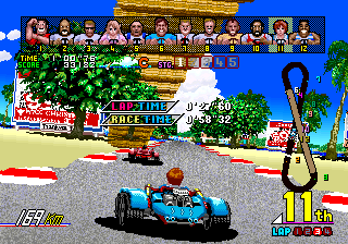
Power Drift is interesting because it is one of the few games I know of which use sprite-based 3d. Each chunk of the track is a small sprite blob,
and the flyby is Sega's way of showing it off. I don't have proof, but I believe games such as F1 Exhaust Heat and RadMobile use a similar system.
It is also worth noting that the deluxe cabinet of Power Drift tilted almost 45 degrees, making it somewhat important to wear that seatbelt for once.
Screenshots from system16.com.
Racin' Force
Racin' Force was reverse-engineered by the intrepid Charles MacDonald. Racin' Force runs on the Konami GX board, which features a daughterboard
with a voxel engine capability. This hardware is based upon older hardware which could only draw a SNES mode 7-like floormap. It was extended
to do a heightmap through this clever technique: It projects not just the tilemap onto a flat 3d plane, but also the height information for
each pixel onto its own separate 3d plane. Then, for each pixel of the screen, it looks up the height information on the projected heightmap, and extrudes each pixel
upwards as necessary. Screenshots from system16.com.
Further Exploration
Here are some sites which may be useful for learning more about pseudo 3d roads:Code Stuff
Formulas and Tips3d Projection
y_screen = (y_world*scale / z) + (screen_height >> 1)
or:
z = (y_world*scale) / (y_screen - (screen_height >> 1))
This formula takes the x or y world coordinates of an object, the z of the object, and returns the x or y pixel location. Or, alternately, given the world and screen coordinates, returns the z location.
The scale determines the field-of-view (FOV), and can be found by:
	scale_x = x_resolution/tan(x_angle/2)

	scale_y = y_resolution/tan(y_angle/2)
Fast Linear Interpolation
o(x) = y1 + ((d * (y2-y1)) >> 16)
This assumes that all the numbers are in 16.16 fixed point. y1 and y2 are the two values to interpolate between, and d is the 16-bit fractional distance between the two points. For example, if d=$7fff, that would be halfway between the two values. This is useful for finding where between two segments a value is.
Fixed Point Arithmetic
Floating point is very expensive for old systems which did not have specialized math hardware. Instead, a system called fixed point was used. This reserved a certain number of bits for the fractional part of the number. For a test case, say you only reserve one bit for the fractional amount, leaving seven bits for the whole number amounts. That fraction bit would represent one half (because a half plus a half equals a whole). To obtain the whole number value stored in that byte, the number is shifted right once. This can be expanded to use any number of bits for the fractional and whole portions of the number.
Fixed point multiplcation is trickier than addition. In this operation, you would multiply the two numbers and
then shift right by however many bits are reserved for fractions. Due to overflow, sometimes you may need to shift
before multiplication instead of after. See "Fast Linear Interpolation" for an example of fixed point multiplcation.
Point Rotation
x' = x*cos(a) - y*sin(a)
Mentioned briefly in the tutorial as being an expensive operation, here is the basic point rotation
formula. As you can see, it's at least 2 table lookups, 4 multiplications, and two additions, but the sine and cosine values can be reused for each point.
Rotating for the purpose of hills would mean rotating the Z and Y coordinates, not the X and Y
coordinates. To find the derivation of this formula, look up Rotation of Axes.
y' = x*sin(a) + y*cos(a)
Avoid Division
Instead of dividing by the z of an object in the standard projection formulas, you can take advantage of some
properties of the road to speed up calculations. Say you have a 3d segment z position and a y position, and you
want to find which line of the screen it belongs on. First, read through the z-map until you get to the
3d segment's z position. Then, multiply the height of the segment by the corresponding scaling value.
The result is the number of pixels above the road that the segment belongs.
Use Z as Scaling Value
Scaling routines work by slowing or speeding up the speed at which
a draw routine reads through graphics data. For example, if you were
to set the read speed to half, this would draw a sprite double the size.
This is because for each time a pixel is drawn, the read position in the
sprite data is only incremented by half, causing the read position to only
increment by a whole number every two pixels.
Usually, a scaling routine has parameters like x, y, and scaling factor.
But since a scaling factor is just 1/z, we can just reuse the Z value of that
sprite! We will still need the scaling factor though to determine the
boundaries of the sprite so that we can keep it centered as it scales.
Glossary
Bad Line - In the C64's VIC II graphics chip, at the first pixel of every background tile, the VIC takes over the processor to pull in more data such as colors. Since there are fewer cycles left for a program to do computations, these are refered to as bad lines
Height Map - A height map is an array of height values. In a polygon or voxel landscape engine, this might be a 2d array (think of a landscape viewed from the top). However, in a road engine, a height map would only need to be one-dimensional (think of a landscape viewed from the side).
Indexed Color Mode - Older systems which feature few colors on the screen at a time are generally in indexed color modes. Some of the most common indexed color modes are the 256-color VGA modes. In these modes, each pixel is represented by a byte. Each byte stores an index value from 0 to 255. When the screen is drawn, the index number for each pixel is looked up in the palette. Each entry in the palette can be one of VGA's 262,144 possible colors. In summary, even though only 256 colors can be on screen at a time, the user can choose each color from a much larger palette.
Linear Interpolation - The process of obtaining in-between values from a data set by drawing lines between the points
Painter's Algorithm - The Painter's Algorithm is the practice of drawing overlapping objects from far to near. This ensures that closer objects always appear on top of farther ones.
Planar Graphics Mode - A Planar graphics mode is one in which an N-bit image is made up of N 1-bit images which are combined to produce the final image. This is opposed to most graphics modes, sometimes referred to as chunky, in which an N-bit image is made up of N-bit pixel values.
Raster Effect - A raster effect is a graphical trick which takes advantage of the scanline-based nature of most computer, or raster, displays.
Scaling Factor - The reciprocal of Z. This gives you the amount by which to scale an object at a given Z distance.
Segment (Road) - I am using the term segment to mean a position below which the road acts one way, and above a different way. For example, the segment could divide a left turn on the lower half of the screen from a right turn on the upper half. As the segment makes its way towards the player, the road will appear to snake left then right.
Segment, 3d (Road) - I am using the term 3d segment to mean a horizontal line which has both a Z distance and a world Y height. Unlike a vertex, which could be a 3d point, a 3d segment would be a 3d line with the left and right X-axis endpoints at positive and negative infinity.
Voxel - A 3d pixel. Raycast/landscape voxel engines were popularized in the game Commanche: Maximum Overkill.
Z Map - A lookup table which associates each line of the screen with a Z distance.
The Gallery
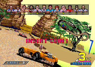
Here is a collection of screenshots that show various ways to do unorthodox road engines. Take a look!Cisco Heat
The hills in this game come at you like a solid wall. The turns are also very exaggerated. The engine seems quite flexible and deals with multiple roads simultaneously, as well as being able to show the height of one road relative to another.
Pole Position
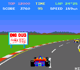
This is the first smoothly running pseudo game I remember. Not extremely impressive today graphically.
Hydra
This is another Atari shoot em up along the lines of Roadblasters. It features a very nice jumping effect in which the road layer's perspective tips, causing the closest objects to fall off the screen. It also nicely projects objects of varying distances above the ground.
Outrunners
This sequel to Outrun is a prime example of rollercoaster-like hills in a racing game. Everything is quite exaggerated in this, and the result is one of the most blinding fast yet nicely controllable racing games ever.
Road Rash
In the 32-bit generation version of Road Rash, everything was textured and buildings were cleverly drawn next to the roadside, leaving some people with the impression that it was a purely polygonal game running fast on the 3do. However, the way objects whip around the corners, buildings warp, and that you can't go backwards would seem to give away that it's not really a polygon engine. The sharp lines on the pavement do hint at some sort of projected segment system though. The tracks have a lot of detail and variety.
The 16-bit generation Road Rash was also no slouch, also featuring a flexible engine with a tiny bit of faked texuring (but was slow).
Turbo

This predates Pole Position and also features hills and bridges. The drawback? There are no transitions from hill to bridge to curve. This used analog graphics scaling hardware.
Spy Hunter II
I don't know what the makers of Spy Hunter II were thinking. Nice idea, bad execution. The road effects seem very similar to Turbo's with a little more in the way of transitions.
Pitstop II
This technique is so quick that on the lowly Commodore 64, people were able to pull off a split screen racing game.
Enduro
Enduro demonstrates the use of pseudo 3d on the Atari 2600.
Enduro Racer
Not to be confused with Enduro, this was a sort of 3d Excitebike-like game. The screenshot shows off the hill technique. Hills are rather sharp, flexible, but generally don't affect the horizon's position, so I'm guessing interpolated points.
Lotus
Lotus comes through with the perfectly curved hill technique. One interesting thing is that Lotus will draw the road's top below the horizon and then fill the gap with a solid color to imply a downhill.
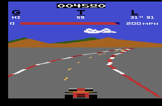
Test Drive II
I'm not sure exactly what to make of Test Drive 2's graphics. While clearly not a polygon racer, it tries very hard to realistically represent a variety of roads. The game is similar to the Need for Speed series but predates it by several years.
Speed Buggy
When you steer in this, in addition to shifting the perspective, the road also slides left and right a little.